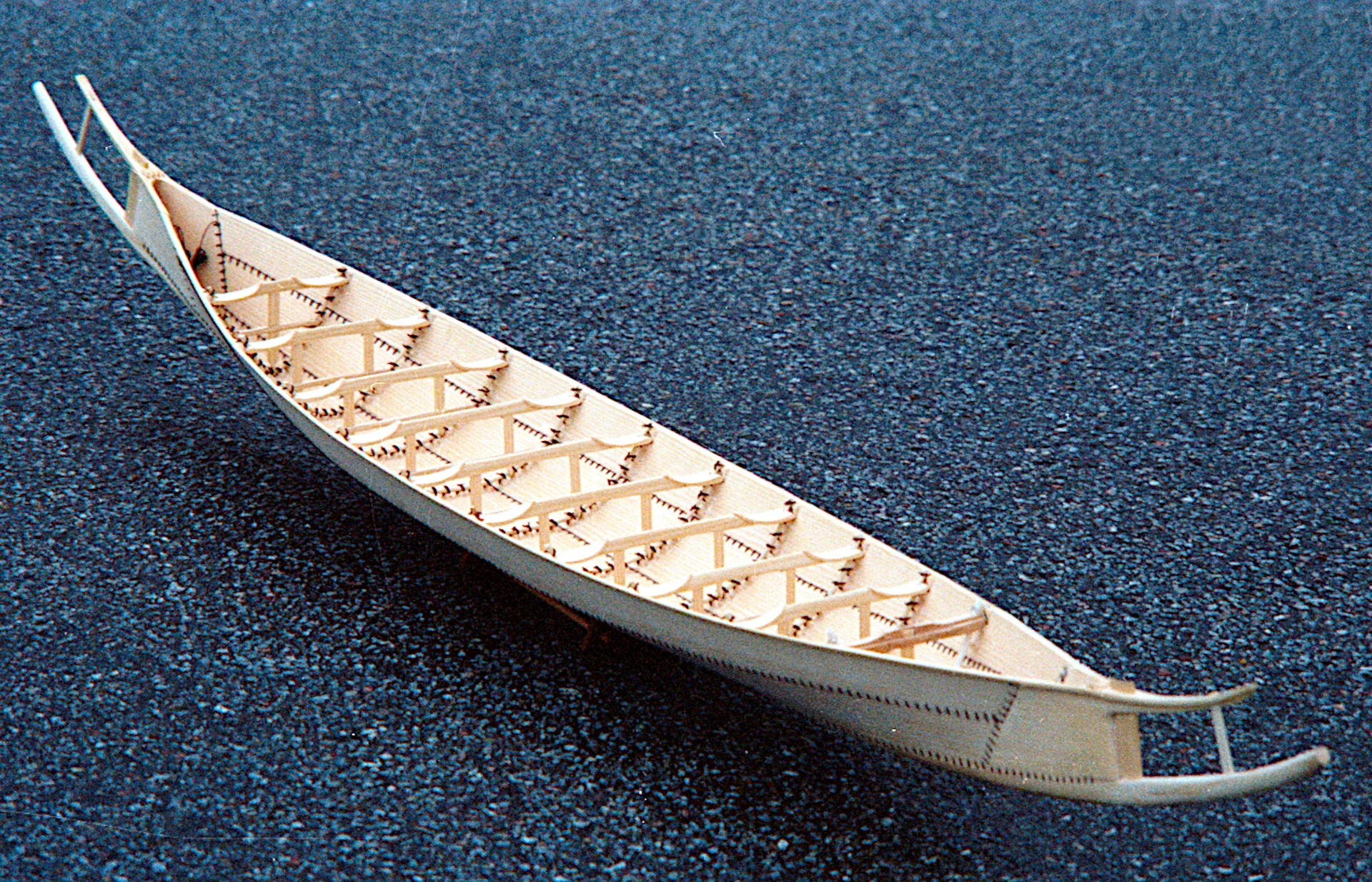
The Hjortspring boat
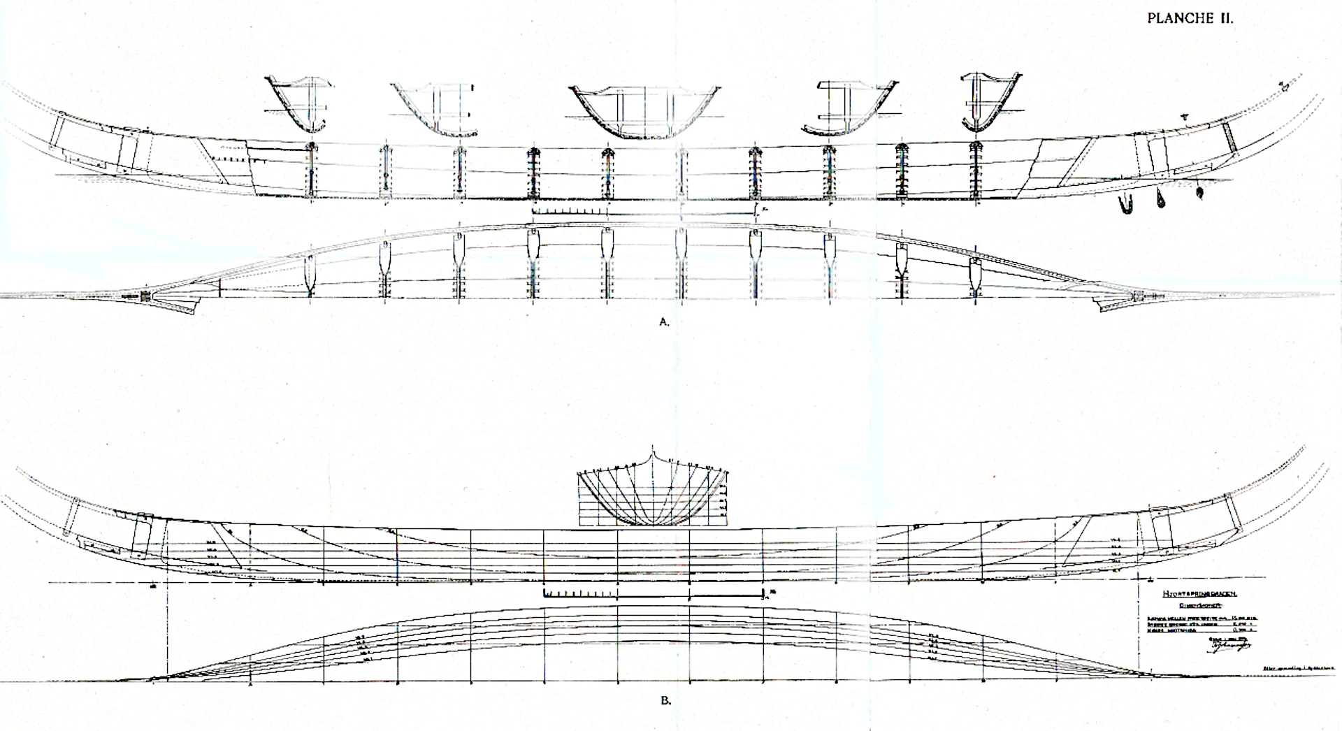
Copies of the original drawings (scale 1:10) were obtained from Oldskriftsselskabet.
Copies of Fr. Johannesen's sketches for the drawings were obtained from the University of Oslo, Department of Archaeology, Art History and Numismatics.
From the National Museum of Denmark's Marine Archaeological Investigations (NMU) in Roskilde, we received measurements that had been the basis for the reinstallation of the Hjortspring boat at the National Museum in 1988.
These drawings were sufficiently accurate for us to start exercises in making elements of the boat and prepare actual construction drawings on our CAD system (AutoCad).
Translated with DeepL.com (free version)
Construction
It was our intention to produce a replica of the boat with respect for the latest interpretations. However, the overall starting point, which these latest assessments also had, was Johannessen's drawings. These drawings, which were in 1:10 scale, were loaded into an AutoCad programme on the guild's computer.
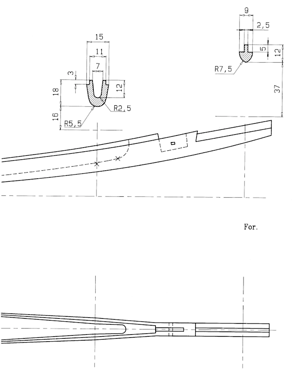
The longest plank in the boat was the bottom plank, which measured 15.4 metres from bow to stern. At both ends, it was finished with the tongue part of a tongue-and-groove joint for attaching the keel horn. In addition, the ends of the bottom plank had a rabbet that guided the stem pieces.
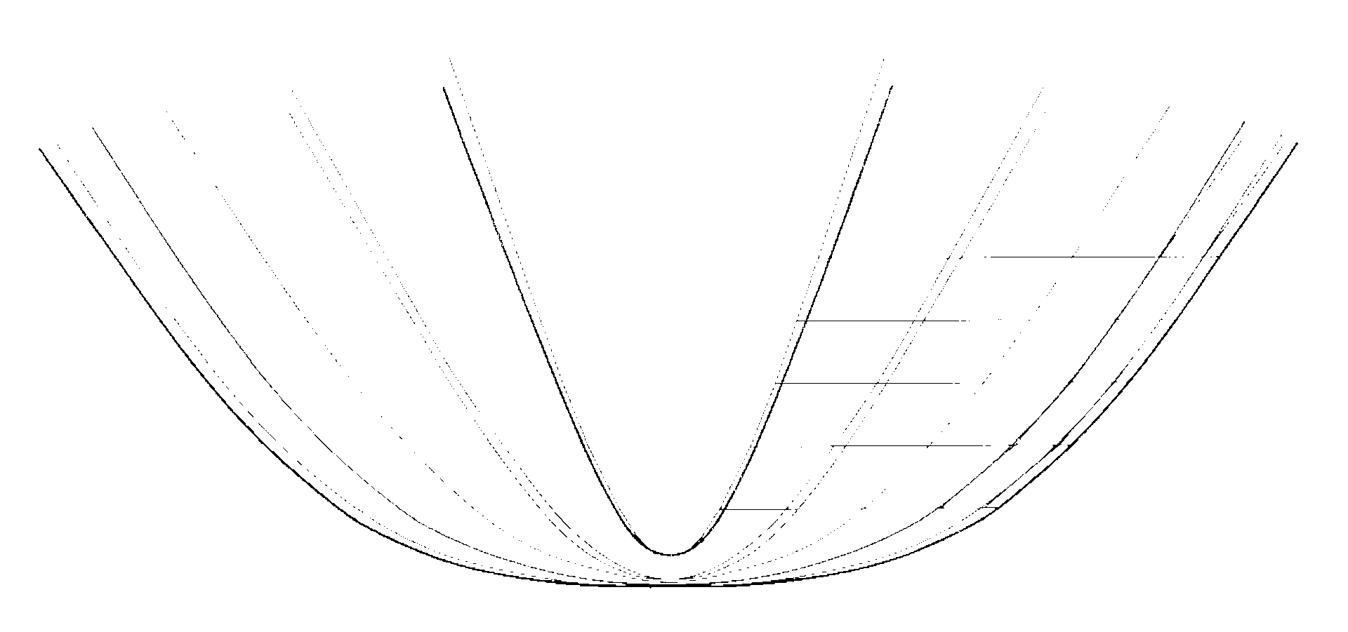
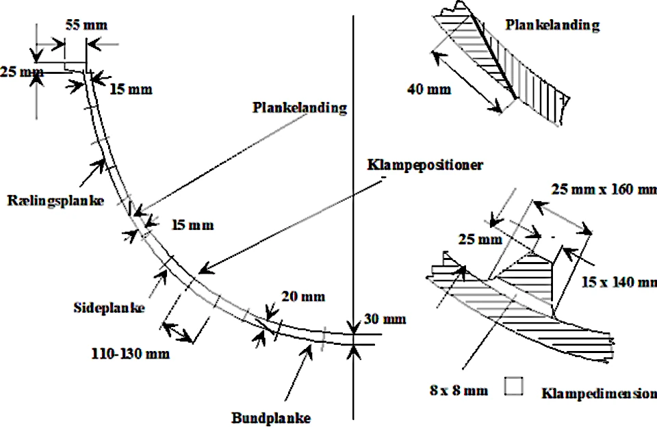
These details were not immediately clear from Johannessen's drawing. Therefore, a 1:1 polystyrene model was made of the end of the bottom plank and the bow. By looking at this model, the most likely design of the joint could be chosen. A key objective was to define the transverse profiles of the boards. These profiles were to be used to produce a series of gauges that would be used to control the carving of the boards.
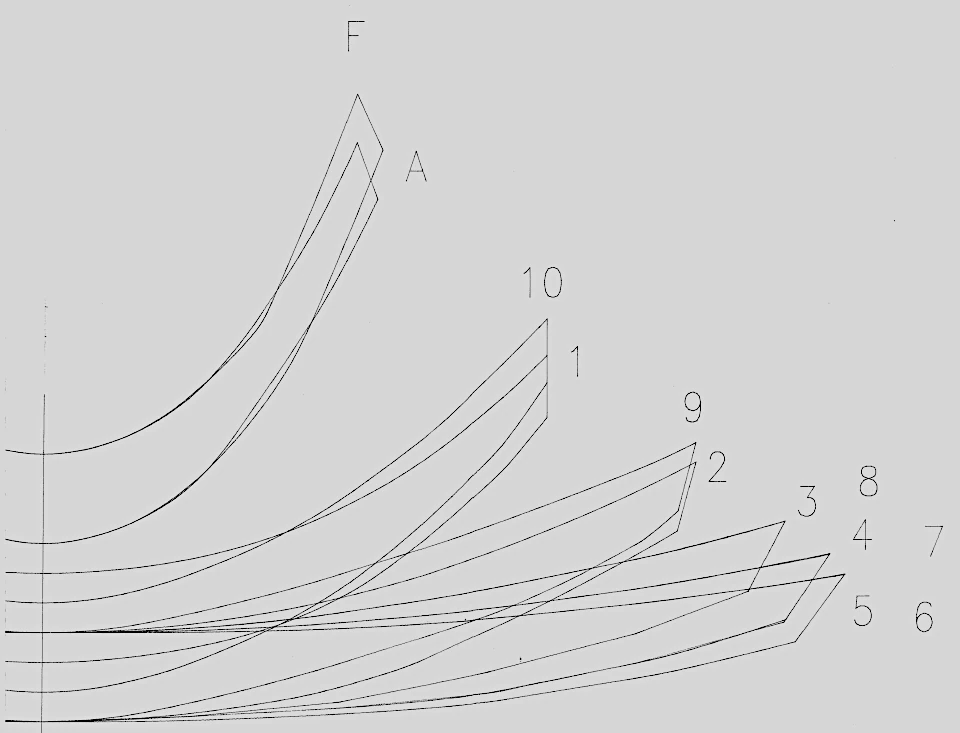
The numbers refer to the frame systems, as there is 1 metre between the frames and frame no. 1 is the rearmost frame. A is 1 metre aft for frame 1 and F is 1 metre forward for frame 10. You can see that there is a slight deviation in the shape of the boat between bow and stern.
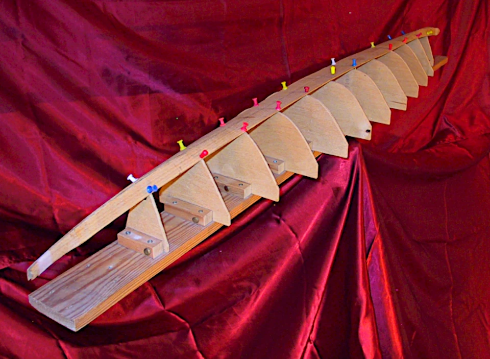
To study the edge shapes of the side and railing planks in the flat state, a 1:10 scale frame model was made in which the frame plates, sawn from computer drawings, were glued to a beam.
The edges of the bottom board were marked on the frame plates. After modelling the planks in thin wood, they could be held against the frame plates. You could see that the side plank was straight on its bottom edge. Its top edge should have a convex arch with an arrow height of 20 cm.
The bottom edge of the railing plank should therefore have a similar curve, but concave.
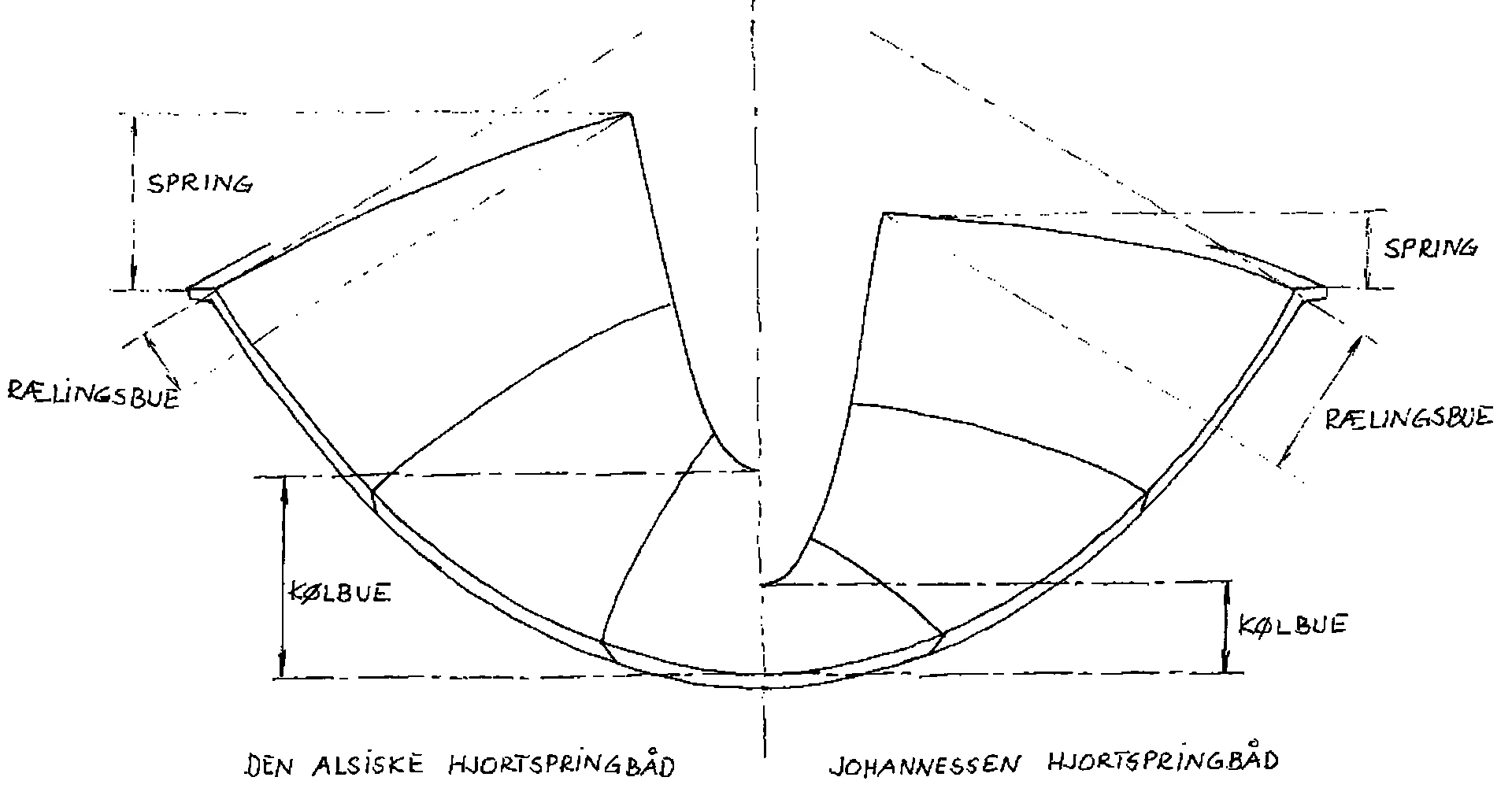
Its upper edge, the railing, should describe an arch with an arrow height of 35 cm in the unfolded state, i.e. before assembly, to achieve the relatively weak sheer that Johannessen's boat had.
The mechanism can be understood as follows. When the plank attached amidships is bent inwards, a straight railing will describe a straight line perpendicular to the plane of the plank and land high up on the bow. Such a small sheer, as indicated by Johannessen, would therefore require a strong curvature of the railing when unfolded. The design team felt that it was unlikely that the timber group, let alone our predecessors, could obtain a tree of such dimensions (or with such a curvature) that a railing plank with a convex curvature of the railing of 35 cm and a concave curvature of the lower edge of 20 cm could be contained within it.
Consequently, preparations were made to allow the railing to curve by only 12 cm, which would give the ship a sheer that was a good 20 cm larger than Johannessen's estimate.
The reason we've paid so much attention to this sheer is because the sheer is crucial to the boat's sailing performance, indirectly at least, as a large sheer pulls the keel line up, giving the boat a more curved keel line.
Finally, the plank thickness and cleat dimensions were chosen.
While the design group studied the shape of the boat, a member of the construction group had made a 1:10 scale model of the boat. This model also emphasised the problem of sheer as a function of the curvature of the rail.


